ブックタイトル「煉瓦造建造物の保存と修復」英語版
- ページ
- 115/138
このページは 「煉瓦造建造物の保存と修復」英語版 の電子ブックに掲載されている115ページの概要です。
秒後に電子ブックの対象ページへ移動します。
「ブックを開く」ボタンをクリックすると今すぐブックを開きます。
このページは 「煉瓦造建造物の保存と修復」英語版 の電子ブックに掲載されている115ページの概要です。
秒後に電子ブックの対象ページへ移動します。
「ブックを開く」ボタンをクリックすると今すぐブックを開きます。
「煉瓦造建造物の保存と修復」英語版
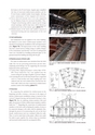
FG1the beams to the H steel beams. Angular pipes simplifiedthe form of structural reinforcement members and theH steel beams enabled smaller beam heights, allowingeasier maintenance of the original roof structure.4 Forces directed inwards were to be also supportedby the Rahmen frame for increased durability. Thus,Y-shaped vertical bracing could be removed and the designaround openings could be kept intact which allowed anunobstructed view of the interior space (photo 7-7) fn 46 .5 Reinforcement of the brick wall enabled removal ofhorizontal bracing and easy maintenance of the roofstructure.? Soil stabilizationSoil stabilization was not applied to the entire building,but limited to areas where reinforcement members wereintroduced, involving the installation of 85 soil improvementpiles (figure 7-8). Soil improvement of the entire buildingmay have caused uneven settling owing to sudden changesin the environment and therefore, the level of undergroundwater was controlled by installing perforated pipes in theground around the building and along side the pits.photo 7-7Inside of the Train Shed after restoration? Reinforcement of brick wallsTwo types of reinforcement were introduced into the brickwalls. One was for preventing destruction and the otheremploying metal fittings was for supporting the structuralframework of the reinforcement.1 Carbon fiber (high-performance carbon fiber UT70-20G (Toray Industries, Inc.) was applied onto thecornices along the top edges of gables to prevent collapse.2 In restoring the arch on the front facade from a segmentalarch to a semi-circular arch, long coupling nuts weresoldered onto the steel reinforcement inserted into thebrick walls, which were then connected to reinforcementmembers inside of the building (photo 7-7).? OverviewBy comparing the methods for reinforcement in thebeginning and after revisions, a decrease in the impact ofinterior reinforcement installation owing to removal of thevertical Y-shaped bracing and horizontal bracing is clear(figure 7-9). Also, by replacing column members with steelpipes, the presence of these reinforcement members could bemade less fn 47 . Regarding the connections of reinforcementmembers to the brick wall, by limiting the number of areas tobe connected, damage to the walls could be minimized. Also,through the process of reconstructing the arch on the frontfacade, reinforcement steel was contained within the walls.Thus, it can be noted that in this project, efforts were madefor made to gear together the various steps in restorationand structural reinforcement for an integrated effect.photo 7-8 Reinforcement steel was introduced in areas of the reconstructedarch(Reference:重要文化財旧手宮鉄道施設(機関車庫三号ほか)保存修理工事報告書)F1,F1AF3A2256751,000(基礎巾)F5779 7797797797791,000675779F2,F3,F4F3B779779 779改良杭の基本間隔(900∮)675F3AFG1F4FG1地盤改良杭900∮基礎:独立基礎F4F1F2F3B既存ピットFG1FG1F3F3BF3BF3FG1地盤改良杭900∮FG1F2F1F3AF5F4FG1FG1F5F1AF3AF4地盤改良杭900∮F5F1FG1F4FG1F3A:試験施工杭figure 7-8 Plot plan of soil improvement piles(Reference:重要文化財旧手宮鉄道施設(機関車庫三号ほか)保存修理工事報告書)鉄骨上端4,320軌条上端320BPL下端Y1G22,060C2Y2b3G2G1G1G1C11,908 1,908b22,252 3,816Y1’Y2Y3Y3C11,488 1,489b2b3イーカプラ継手位置figure 7-9 Sectional plan after structural reinforcement(Reference:重要文化財旧手宮鉄道施設(機関車庫三号ほか)保存修理工事報告書)2,0002,977Y4Y4C13,542C1Y5CG1113